


- Product Details
Dual Drive Balancing Machine
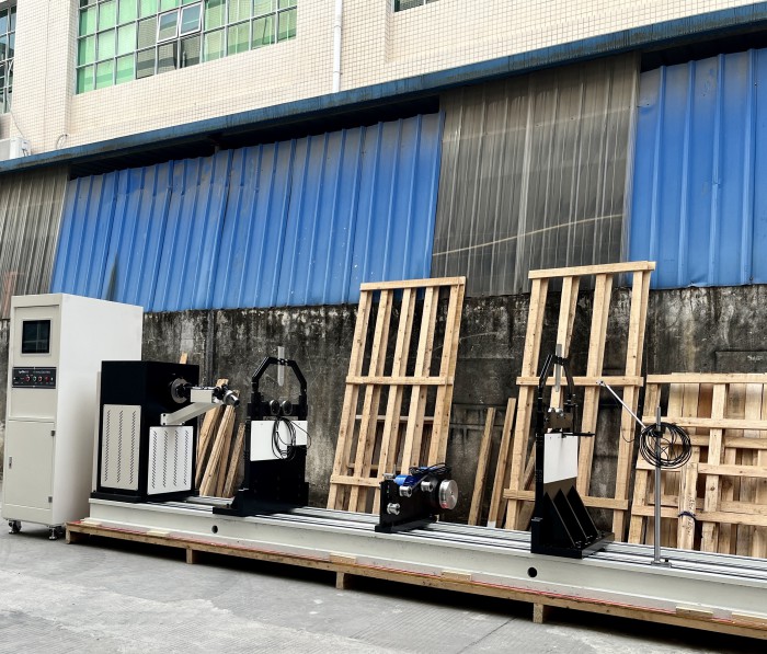
Equipment Overview
Dual-drive balancing machine with a universal joint transmission structure and a belt type structure, which is widely used in motors, fans, Paper, steel, automobile, aviation and other industries.
Before operation, as long as the distance between the two correction surfaces of the workpiece to be calibrated, the distance between the correction surface and the support point and the corrected radius data are set, the unbalance amount and the corresponding phase value of the workpiece can be correctly displayed at one start.
Features:
1. Dynamic and static balance, up to 10 support methods, weight removal, forward and reverse rotation can be flexibly customized.
2. Using multiple calibration coefficient combinations, dual software and hardware filtering, and high-speed data compression, the measurement is more stable, accurate, and faster.
3. The balance amount and angle unit of the measurement display can be customized, and the display accuracy can also be customized to achieve real-time unit conversion to meet different customer needs.
4. With clamp compensation function,
5. The calibration process is perfect, the calibration interface is professional and easier to maintain, the calibration coefficient is verified in real time, and it is equipped with a system linear diagram.
6. Two languages, the display language and the printing report language have two options: Chinese and English.
7. Easy to operate, the measured value display uses a combination of numbers and vector graphics, all system parameters have prompt information, including parameter definitions and setting ranges, and the calibration process has a full wizard.
8. Massive data storage, database storage, no limit to the number of rotor data, fixture compensation data records, and 10,000 cycle records of measurement records.
9. Historical recording, automatically records historical measurement values, the recording method can be selected, and the personalization is strong.
Basic principles and functions
The balanced workpiece is horizontally supported on the swing frame. The belt rotates the workpiece in a certain way, and the unbalanced mass generates centrifugal force to excite the swing frame to vibrate. The vibration sensor converts the vibration signal into an electrical signal and inputs it into the electrical measurement system, while the photoelectric sensor provides a frequency/phase reference signal for the system.
The division of labor between system software and hardware is as follows: the hardware completes the processing tasks of vibration signals, making the system have good real-time performance; the software completes calculation, control and other extended functions.
Signal preprocessing uses a multi-order integration circuit to suppress noise and improve the signal-to-noise ratio. Programmable amplifiers change gain under computer control based on unbalanced signal levels.
The narrowband tracking filter completes the signal-to-noise separation of the signal under test.
The A/D converter samples and quantizes the filtered signal (unbalanced signal) and inputs it into the computer. It also completes the collection of other signals (such as system self-test and rotational speed signal).
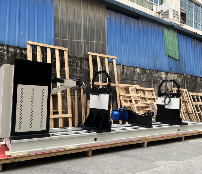
structure
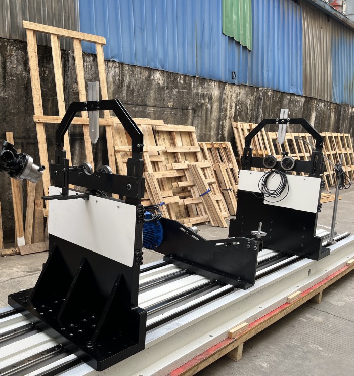
This machine consists of three parts: bed, support frame and drive system.
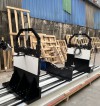
1. Lathe bed part: desktop square base, used to support various components of the support frame (support frame, drive frame, safety frame.)
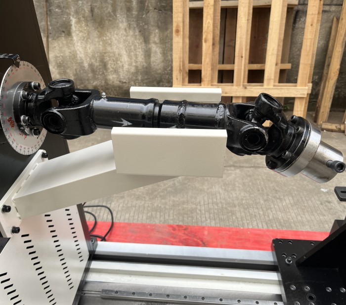
2. Left and right support frames: fixed on the base. Loosen the screw and move horizontally through the guide key to adjust the distance to suit the balance of parts of different lengths.
3. Roller bracket: placed on the left and right support frames, using two pairs of rollers to support balancing parts. Keep coaxiality and equal height during assembly.
4. Vibration sensor: placed at the rear end of the support frame and connected to the bridge with a connecting rod to sense the signal generated by imbalance.
5. Drive system: This machine adopts motor drive mode.
6. Install 2 sets of standard support swing frames on the bed
Main features:
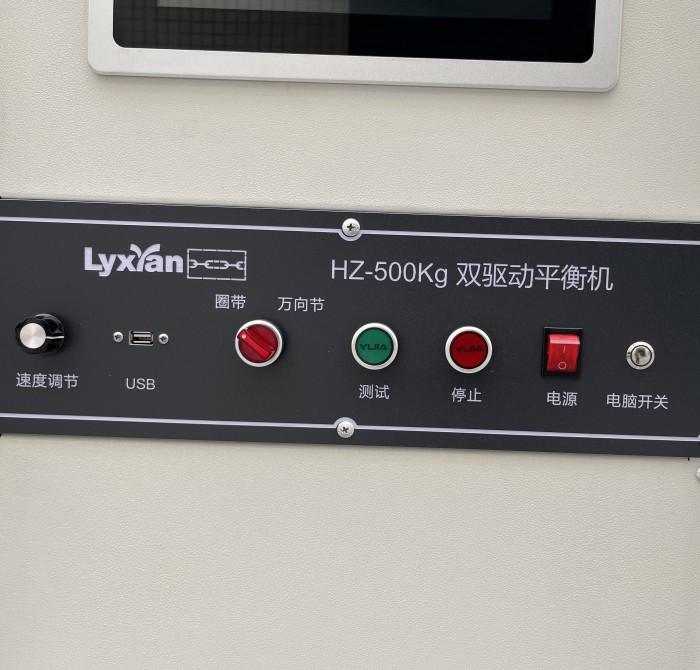
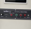
Touch screen operation
lFriendly human-machine interface makes operation more convenient.
Chinese and English display
lThe display language can be selected from Chinese and English.
Intuitive interface
l1.The measurement value display is a combination of numbers and vector graphics. Vector graphics can quickly sense the magnitude and angle of imbalance. The scale value of the graph can be adjusted to facilitate setting various levels.
l2.All system parameters have prompt information, including parameter definition and setting range. It is convenient for users to get started quickly.
l3.Automatically determine whether the rotor is qualified, with color prompts.
l4.The calibration methods are flexible and diverse, and the process is also guided by wizards. The professional calibration interface makes maintenance easier.
High display accuracy
lMinimum resolution 0.001mg.
Single and double sided dynamic balancing measurement
lDouble-sided dynamic balance, single-sided static balance and dynamic and static balance methods are available for measurement.
Various support methods
lThe traditional 10 types of double-sided support and single-sided support methods have a wider range of applications.
Various solution methods
lIt has two solution methods: mathematical test weight method and influence coefficient method, and is suitable for various hard-support and soft-support balancing machines.
Sensor detection
lIt can diagnose whether the sensor or sensor is faulty and avoid false balance of the workpiece.
electrical compensation
lWith electrical compensation function, the ordinary rotor can be tested as a calibration rotor, which is suitable for various working conditions. Debugging is more convenient and the system model is more in line with the actual situation.
Indexing function
lSolve the balance problem of the blade rotor and directly display the imbalance amount on each blade.
Unbalance calculation
The software complies with the ISO1940 standard and has built-in allowable imbalance calculation. By inputting the relevant parameters of the workpiece, the allowable imbalance of the workpiece can be directly calculated. It will automatically determine whether the workpiece is qualified and is less than the set value. The interface value position will display OK.
Waveform display
lYou can view the waveform amplitude of the collected signal.
USB data export
lMeasurement data can be exported through USB flash drive.
100 sets of rotor data storage
lThe rotor data can be saved for easy recall for the next measurement.
Data printing
lThe printed report includes rotor parameters, calibration surface information, qualification criteria, measurement data, vector diagrams and qualification determination information, in A4 paper format.
Unbalanced weight unit customization
*The measurement unit g-g.cm-g.mm can be switched as needed.

