Simple Tensile Wedge Grips

Fig. 1: 10,000 lb. capacity Simple Wedge Grip for 1 in. wide flat specimens, 1.5 in. grip length.
There are two basic types of mechanical wedge grips. Either the wedges move axially as they tighten on the specimen and the bodies of the grips remain stationary, or the grip bodies move axially and the wedges remain stationary while being tightened on the specimen. The former are termed Simple Tensive Wedge Grips and the latter are termed Standard Tensile Wedge Grips.
An example of a Simple Wedge Grip is shown in Fig 1. Note that a screw on each side of the grip, pushing on a plate against the tops of the wedge grip inserts, is used to tighten the grip onto the specimen prior to the test.
The Simple Wedge Grips are slightly easier to fabricate and thus are slightly less expensive. Their major advantage, however, is when vertical space in the load frame is limited, or when the test is to be performed in an oven or environmental chamber. Since Simple Wedge Grips do not have the opposing handles for opening and closing the wedges, their overall length is considerably less.
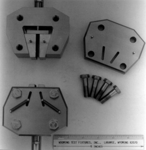
Because the wedges move axially relative to the specimen during clamping, the Simple Wedge Grips, have the potential to accidentally place the tensile specimen into compression during installation, possibly damaging it as the second grip is tightened. Note, however, that when using Simple Wedge Grips it may be possible to grip the upper end of the test specimen and then disconnect the lower grip from the testing machine while engaging the specimen, thus avoiding this potential problem. For example the grips shown in Fig. 1 have slip-fit connections such that when the connecting pin is removed, the grip is disconnected from the load frame.
As a loading is applied to the test specimen, the wedging action takes over, to grip the specimen in proportion to the magnitude of the load being applied, just as for a standard grip. The springs retract the grip inserts when the grips are opened by backing out the screws.
Fig. 2 shows a similar simple grip, but with the tightening screws in the top of the grip (out of sight here). This is an option when the grips are sufficiently thick. Although the screws cannot be seen in this photograph, the push plate can. Note that this grip has V-grip inserts mounted in it, for gripping round specimens. All types of grip inserts can be provided

Fig. 2: 15,000 lb. capacity Simple Wedge Grips with tungsten carbide particle coated V-grips for round specimens.
Fig. 3 shows an example of Simple Wedge Grips with top screws and pusher plates. These grips are for wide specimens such as for geotextile materials tested as per ASTM D4595.
Fig. 3: 4 in. wide Simple Tensile Wedge Grips, 1,000 lb. capacity.
Sometimes space is very limited, such as when performing tensile testing at cryogenic temperatures in a dewar. Fig. 4 shows 20,000 lb capacity compact wedge grips fabricated of 310 stainless steel.
Fig. 4: 20,000 lb. capacity compact Simple Tensile Wedge Grips made of 310 stainless steel for use at cryogenic temperatures.
A less commonly used version of simple wedge grips is shown in Fig. 5. Rather than using screws at either the top or at the sides of the grip body to push the wedges against the test specimen, these grips have a hand wheel to tighten the wedges onto the specimen.
Fig. 5: Simple Tensile Wedge Grips with hand wheels for tightening the wedges, 5,000 lb. capacity, 1 in. wide.


