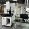
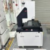
- Product Details
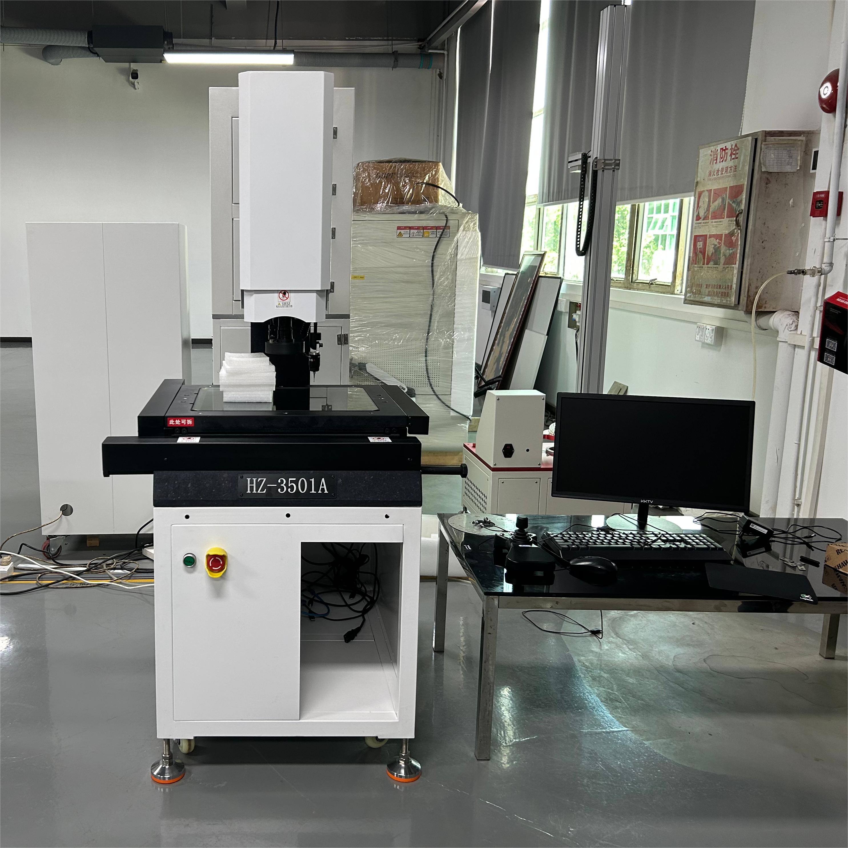
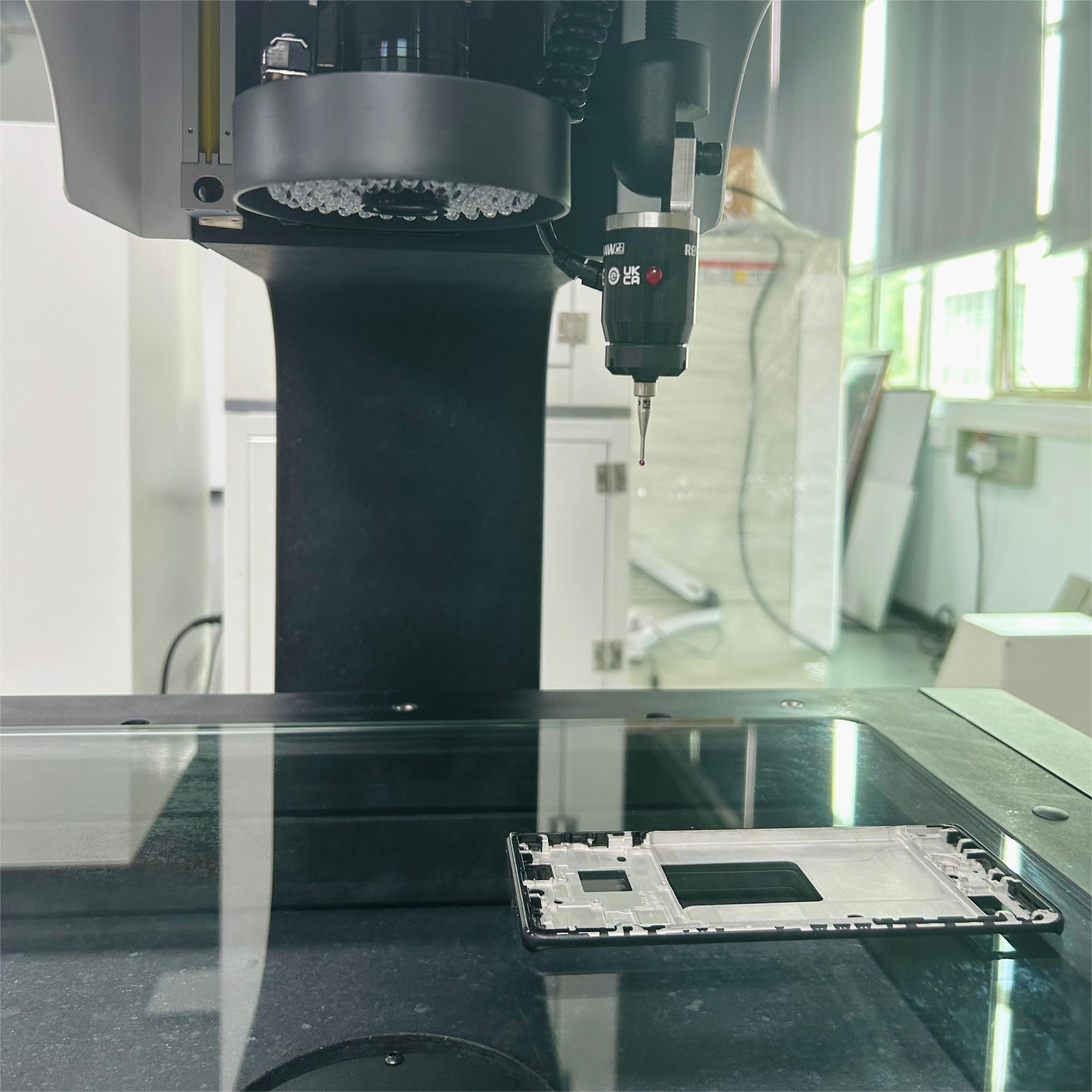
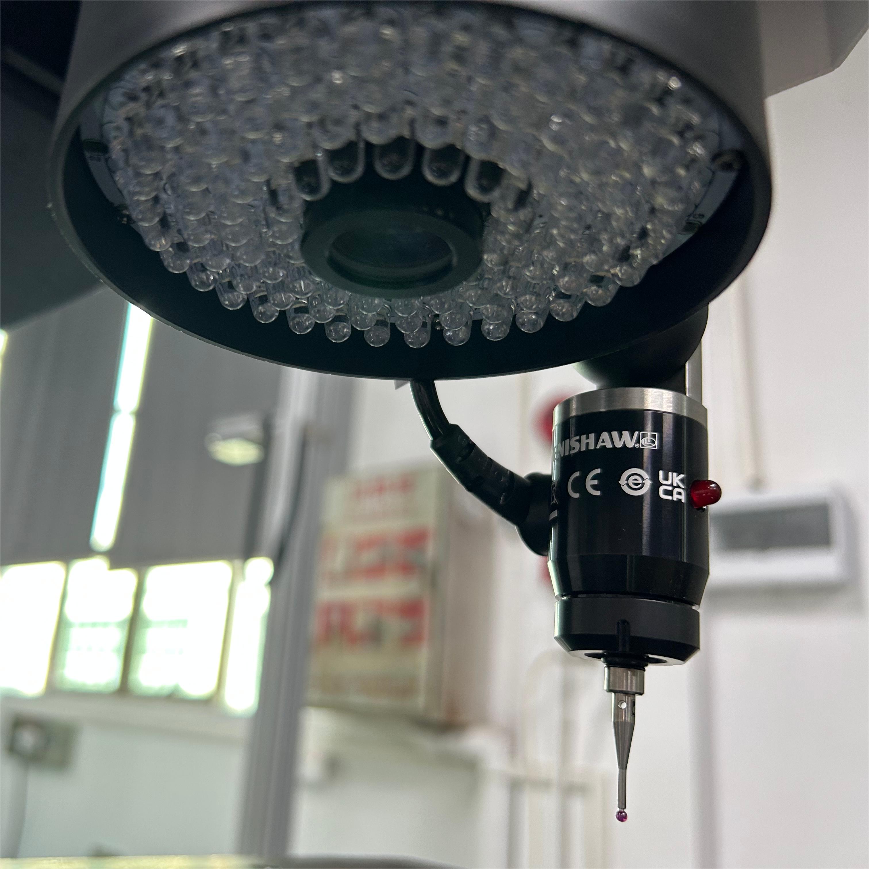
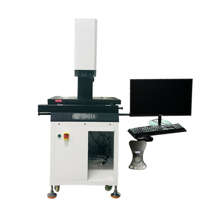
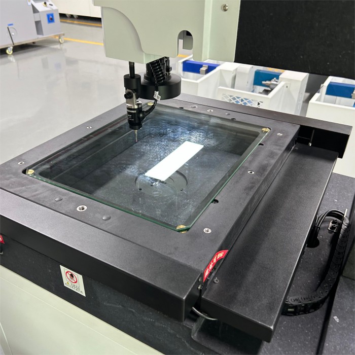
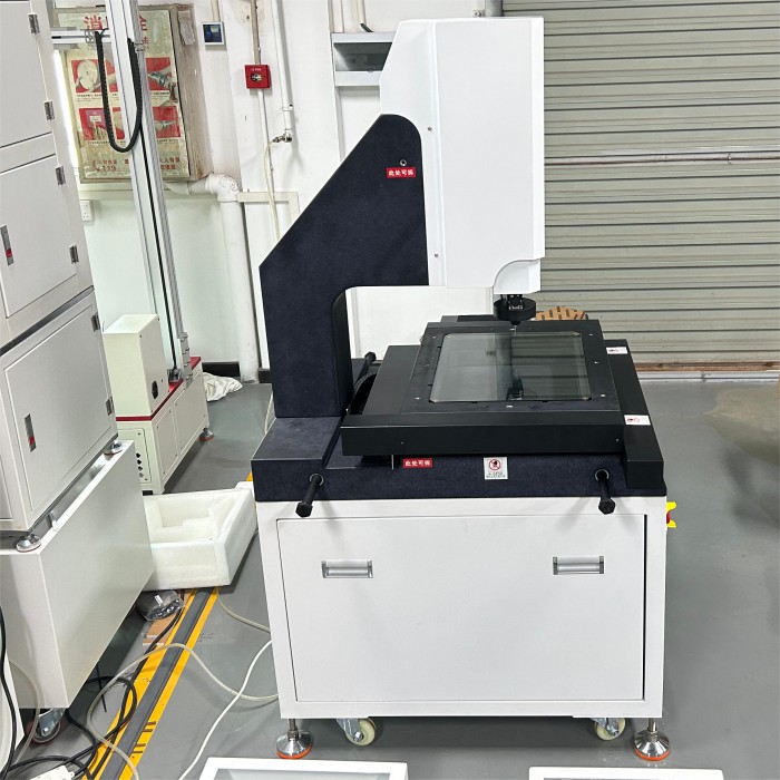
The fully automatic image measuring instrument is an artificial intelligence-based modern optical non-contact measuring instrument developed on the basis of the digital image measuring instrument (also known as the CNC imager). The fully automatic image measuring instrument inherits the excellent motion accuracy and motion control performance of the digital instrument, integrates the design ingenuity of the machine software, and is a cutting-edge optical size detection equipment today.
Equipment Summary:
This instrument is applicable to two coordinates measuring for the purpose of all fields of application, machinery, electronics, instruments, plastic etc widely used.
Main Feature:
1, zoom ShiZiXian generator as objective and measuring aiming system,
2, image measuring instrument has a variety of data processing, display, input and output functions, especially the workpiece adjust function very practical,
3, high resolution 9 segments, change the objective set times not to reconsider avaiable selection scale
4, image measuring instrument spare R232 interface, after connect with computer, using special measuring software can be processed on surveying and mapping graphics and output
Main Fuction :
1, can be made into a product photographs and products to jpeg formats stored in computer form product library
2, and will be stored in computer photos in open and in real-time images of the same picture were compared
3, graphics, can input to AutoCAD become engineering drawings
4, AutoCAD standard engineering drawings can input real-time image, making AutoCAD engineering drawings and the actual shape overlap, comparing the workpiece so as to find out the difference between the workpiece and engineering drawings
5, can input previously photos stored jpeg image to real-time image with actual workpiece overlap contrast
6, a bird's eye view of the map in size to mark
7, custom round: according to customer needs a home-grown standard circular, again with standard circle and the workpiece do overlap contrast images, so as to find the workpiece and standard circular errors between
8, custom hidden-lines: to define the starting point coordinates interval-number, length, rotating Angle, again with images of workpiece as overlap contrast, so as to find the workpiece and standard graphic errors between
9, sets up the real-time image coordinates customer: the actual workpiece set automatically coordinates -1.0, in picture arbitrary point on the labeling accepts the X, Y coordinates
10, coordinates the label to direct the coordinates of -1.0 as a benchmark, tagging picture arbitrary point coordinates
11, patent take R Angle function: for the present market condition accurately plane take R Angle way
12, measurements: measurable plane geometry size (any Angle, diameter, radius, point to the line of the distance and two round eccentric, two spacing, etc.)
13, drawing: but will live video the actual workpiece appearance were portrayed, form complete engineering drawing, drawing mode and AutoCAD similar
14, mark: can the workpiece in real-time image indicated size. (length and Angle, diameter, radius, point to the line of the distance and two round eccentric, two spacing, etc
Measured rendering
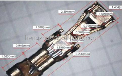
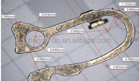
1 | Model No |
|
2 | Main body size | 540*560*850mm |
3 | Table of metal | 300*250mm |
4 | Glass counter size | 220*160mm |
5 | Actual working travel | 150*100*80mm |
6 | Main body weight | 110KG |
7 | Machine bottom sit | High precision granite base and bar |
8 | Linear precision | (3+L/150)um |
9 | Surface lighting | LEDThe annular ultra bright cold light(Brightness adjustable) |
10 | Outline lighting | LEDUltra bright circular lamp(Brightness adjustable) |
11 | Calculating measurement functions | REICA 2.5DPrecision measuring system software |
12 | Resolving power | 0.001mm |
13 | Repeat precision | 0.003mm |
14 | CCD | SONY chip 1/3 colorfulCCD |
15 | eyepiece | 0.5X(optional 1X,2x) |
16 | objective | 0.7X~4.5X magnifacation 20X~120X |
17 | Power supply | AC90~264V 50/60Hz |
18 | truck | 30KG |
